
Test rig and measurement equipment
A continuous condition monitoring (CM) for defect detection of drive elements can reduce maintenance costs and significantly increase the safety of the application.
In practice, the analysis of vibrations is the predominant method to diagnose damages in rolling bearings. Current research focuses on condition monitoring by using the motor current signals of the electric driving machine. The particular aspect of the method presented here is that the drive motor is used as a sensor, thus making the implementation of additional expensive sensor technology superfluous. The objective is to identify defective bearings by the signature of the stator current signal.
The purpose of the test rig is the reproduction of relevant faults and damages so that the required data base can be obtained through experiments. The data base provides the basis for the development, validation and training of diagnostic algorithms for condition monitoring of rolling bearings.
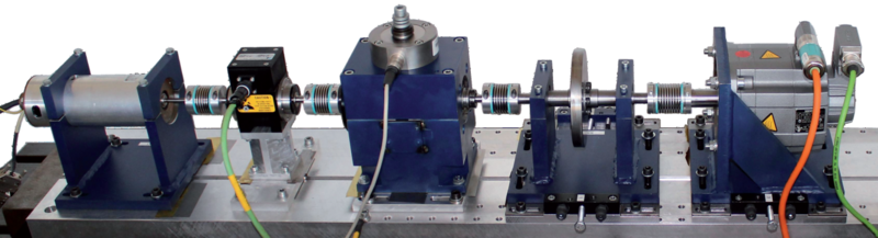
The test rig is a modular system generating the measurement data required for the analysis of corresponding signature and damage characteristics derived from motor current signals. The basic components of the test rig are the drive motor (a permanent magnet synchronous motor) acting as a sensor, a torque measurement shaft, the test modules and a load motor (synchronous servo motor).
The modular setup ensures a flexible application for the analysis of various mechanical defects and damages. Misalignment and tilting of the bearing shafts and of gearing are constructively integrated into the modules of the test rig. Component damages to rolling bearing and even gearing, caused by e. g. wear, can be used in the test rig as artificially damaged machine components.
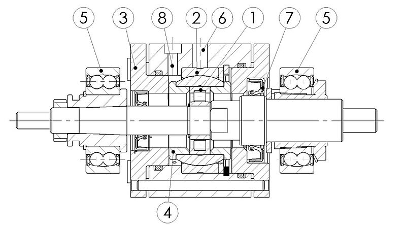
Grooved ball bearings and cylindrical roller bearings of type 6203, N203 or NU203 can be inserted in the rolling bearing test module. By using cylindrical roller bearings, damages to the removable inner as well as to the outer ring can easily be introduced. A distinction is made between real bearing damage and artificially damaged bearings. The real bearing damages are generated in an accelerated lifetime test rig by pre-defined continuous loads (see accelerated lifetime test rig). Artificially damaged bearings on the other hand are damaged by conventional machining processes such as drilling or eroding.
The stator current at the drive motor and the housing vibrations in the form of acceleration at the bearing housing are the main measurement variables in the bearing test stand.
Technical data (Test rig for condition monitoring of rolling bearings)
Drives:
Hanning synchronous motor: 425 W, 3,000 1/min, 1.35 Nm
Siemens synchronous servomotor: 1.7 kW, 3,000 1/min, 6 Nm
Current measurement:
current transformer LEM type CKSR 15-NP, Bessel-Filter 4th order with a filter frequency of 25 kHz
Vibration measurement:
vibration sensor: Model No. 336C04 (PCB Piezotronics Inc.), Kistler
Additional measuring instrumentation:
measuring shaft: Magtrol TM 305
force measurement: measuring box K11 (Lorents-Messtechnik)
charging amplifier type 5015, filter 30 kHz (2nd order)
temperature measurement: temperature sensor MINI MCR-SL-TC_UI-NC (Phoenix Contact)
hardware: Processor-Board DS 1006 Single Core (with DS2004) (dSpace GmbH)