
Welcome to the Chair of Engineering Mechanics
The development and manufacture of innovative products using new materials requires in-depth knowledge of analytical and numerical calculation methods for the safe design of components and machines. Imparting this knowledge is one of the main tasks of the Chair of Structural and Materials Mechanics in the Bachelor's and Master's degree programmes. The combination of training, modelling, experiment and application at SWM prepares future engineers in several layers for the ever-increasing challenges in the calculation of mechanical engineering components in industry.


Sekretariat
Simone Hillermann
Structural and material mechanics
Pohlweg 47-49
33098 Paderborn
Office hours
Mo - Do: 11:30 bis 15:30 Uhr
Fr: 09:00 bis 13:00 Uhr
Arbeitsgruppe FAM
Die Arbeitsgruppe für Angewandte Mechanik (FAM) ist Teil des Lehrstuhls für Struktur- und Werkstoffmechanik und lehrt und forscht im Bereich der Struktur-, Bruch- und Biomechanik. Dabei stehen drei Hauptziele im Vordergrund:
- eine solide und anschauliche Lehre
- eine grundlegende aber praxisnahe Forschung
- und eine umfangreiche Zusammenarbeit mit regionalen und internationalen Industrieunternehmen
Im Bachelor- und Masterstudium werden vertiefte Lehrveranstaltungen angeboten, u. a. in:
- Strukturanalyse 1 & 2
- Betriebsfestigkeit
- Fatigue/Schadensanalyse
- Numerische Methoden in der Produktentwicklung 1 & 2
- Biomechanik
- Technische Orthopädie
Die Vernetzung mit der Industrie sorgt für einen praxisnahen Bezug in Lehrveranstaltungen
Die Forschung am Lehrstuhl umfasst mehrere Schwerpunkte:
- Spannungs- und Verformungsanalysen, insbesondere im Leichtbauumfeld
- Strukturanalyse komplexer Bauteile unter mechanischer und thermischer Belastung
- Experimentelle Bruchmechanik: z. B. Lebensdauer- und Bruchvorhersagen
- Numerische Risswachstumssimulationen, z. B. bei Ermüdungsrissen
- Risswachstum in Strukturen bei komplexen Beanspruchungen (Mixed-Mode)
- Biomechanik: Von Knochenstrukturabbildung über Bewegungsabläufe bis hin zur technischen Orthopädie
- Additive Fertigung: Einsatz und Optimierung additiver Verfahren, z. B. in Kooperation mit dem Direct Manufacturing Research Center (DMRC) der Universität
- Industrieprojekte / Technologietransfer: Intensive Zusammenarbeit mit Wirtschaftsunternehmen zur Bauteiloptimierung, Bruchsicherheit und Produktentwicklung
Mehr über die FAM erfahren Sie hier


Experimental Laboratory
10 kN universal testing machine
| Component manufacturer: | MTS |
| Software: | MTS 793 and Test Suite MPE |
| Drive: | servo-hydraulic |
| Maximum axial load: | ± 10 kN |
| Maximum piston stroke: | 100 mm |
| Actuators: | 1 axial cylinder |
| Max. Test speed: | 250 mm/s |
| Minimum clamping length: | 0 mm |
| Clamping device: | 2 kN MTS Advantage Pneumatic Grips |
| Clamping range flat: | 0 - 10 mm |

100 kN universal testing machine
| Component manufacturer: | MTS |
| Software: | MTS 793 and Test Suite MPE |
| Drive: | servo-hydraulic |
| Maximum axial load: | 100 kN |
| Maximum piston stroke: | 150mm |
| Actuators: | 1 axial cylinder |
| Max. Test speed: | 200 mm/s |
| Minimum clamping length: | 0 mm |
| Clamping device: | 100 kN MTS 647 Hydraulic Wedge Grips |
| Clamping range flat: | 0 - 7.6 mm |
| Clamping range round: | ø 15, ø 25 ø 10.92 - 16.51 mm in V-notch |

MTS Bionix 370.02 Axial-Torsional
| Software: | MTS 793 and Test Suite MPE |
| Drive: | servo-hydraulic |
| Actuators: | 1 axial cylinder 1 rotary cylinder |
| Maximum axial load: | 25 kN |
| Maximum torque: | 222 Nm |
| Maximum piston stroke: | 100 mm |
| Maximum angle of rotation: | 270° |
| Maximum test speed: | 300 mm/s |
| Maximum rotation speed: | 400 °/s |
| Minimum clamping length: | 0 mm |
| Clamping device: | 25 kN MTS 647 Hydraulic Wedge Grips |
| Clamping range flat: | 0 - 24 mm |
| Clamping range round: | ø 10, ø 15, ø 25 |

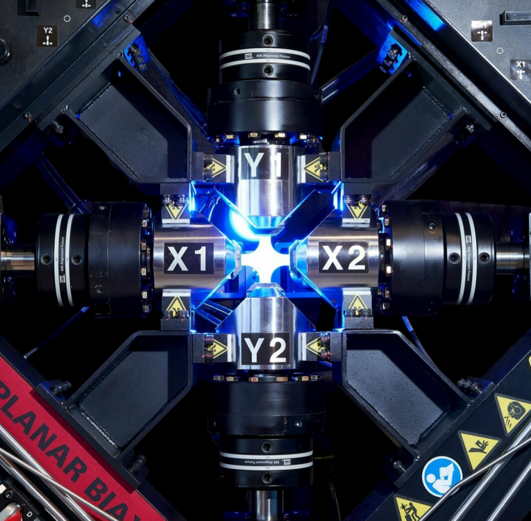
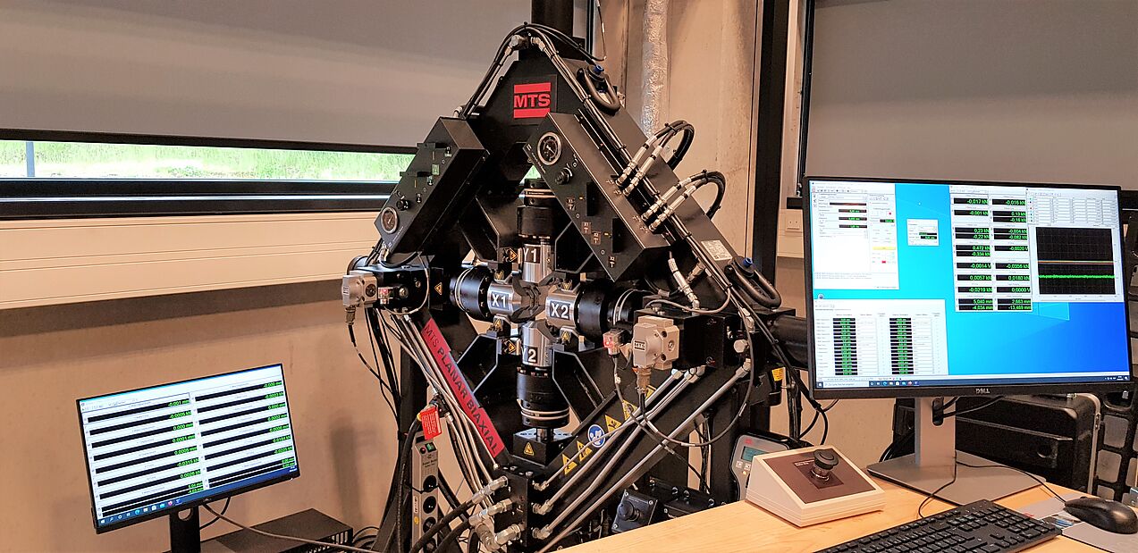
MTS Planar Biaxial 25 kN x 25 kN "BIAX"
| Software: | MTS 793 and Test Suite MPE |
| Drive: | servo-hydraulic |
| Maximum axial load: | 25 kN per axis |
| Maximum stroke: | 103 mm per axis |
| Actuators: | 4 axial cylinders (2 per axis) |
| Max. Test speed: | 600 mm/s per axis (without test specimen) |
| Minimum clamping length: | 34 mm per axis (= 103 mm possible stroke) |
| Clamping fixtures: | 25 kN MTS 647 Hydraulic Wedge Grips |
| Clamping range flat: | 0 - 4.2 mm 3.5 - 7.5 mm |
GOM Aramis SRX
| Evaluation software: | GOM Correlate 2021 |
| Resolution: | 4096 x 3068 px (12 M) |
| Measuring volumes: | 130 x 100 x 40 mm³ 550 x 440 x 400 mm³ |
| Detection frequencies: | |
| Full screen: | 75 Hz |
| 2/3 picture height: | 115 Hz |
| 1/3 picture height: | 230 Hz |
| 1/6 picture height: | 480 Hz |
| HD field: | 490 Hz |
| Illumination: | Polarised (insensitive to ambient light) |
The SWM has two identical Aramis systems and is therefore able to record experiments in a so-called multi-sensor setup. This means that the two sensors detect the sample synchronously from different directions and can therefore detect opposing sample surfaces, for example. This allows, for example, the necking of a tensile sample to be precisely determined and the volume expansion to be calculated.
It is also possible to record a larger sample area with a consistently high resolution. The two measurements are then handled and analysed as a single measurement.


GOM ATOS II
| Variants | SO 400 |
| Analysis software: | GOM Correlate 2021 |
| Resolution: | 1280 x 1024 px |
| Measuring volumes: | 65 x 52 x 30 mm³ 350 x 380 x 280 mm³ |
Samples that are difficult to measure tactilely due to certain geometries and material properties can be precisely digitised and analysed with this 3D scanner, for example for subsequent stress calculation.
Their condition can also be documented as a surface model both before and after the test, so that the deformation caused by the experiment can also be analysed.
With the help of a surface comparison, an existing CAD model can be compared with the scanned surface in order to check the production quality of samples, for example.


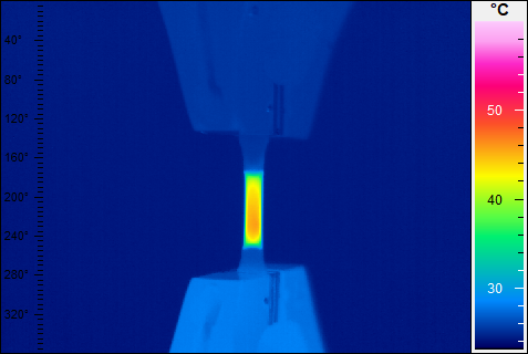
Infratec VarioCAM® head HiRes 640
| Evaluation software: | IRBIS® 3 professional |
| Temperature range: | -40 - 1200 °C |
| Spectral range: | 7.5 - 14 µm |
| Resolution: | 640 x 480 |
| Temperature resolution: | better than 0.05 K |
| IR image frequency: | 50 Hz |
| Measurement accuracy: | ± 1.5 K (0 to 100) °C; ± 2 % (< 0 or > 100) °C |
| Detector: | Uncooled microbolometer FPA |
| Objective lens: | Standard objective 1.0/30 mm |
| FOV: | 30° x 23° |
| Focus: | 0.3 m to infinity |
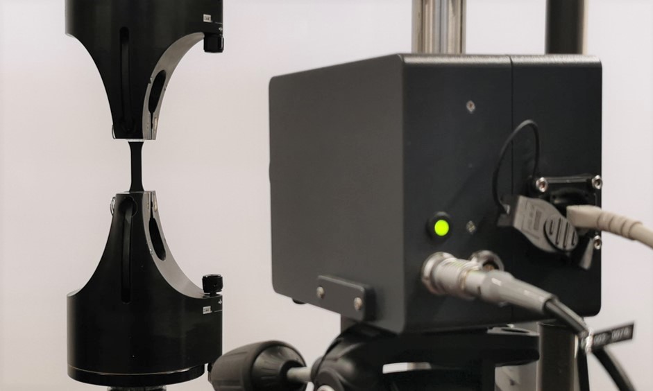
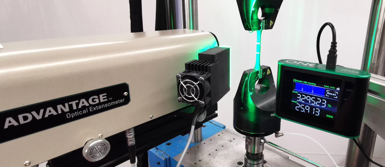
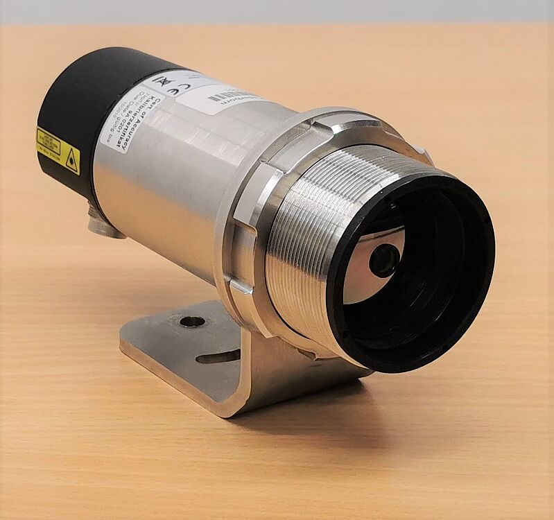
MTS Advantage Optical Extensometer
| Model: | ONE-78PT-200 |
| Functionality: | non-tactile (optical) |
| Optics: | telecentric |
| Maximum sampling rate: | 3 kHz |
| FOV (vertical) | 78 mm |
| Measuring lengths: | 10 - 65 mm |
| Maximum elongation: | 580 % |
| Illumination: | Polarised (insensitive to ambient light) |
| Suitable for strain control |
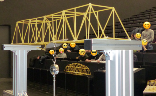
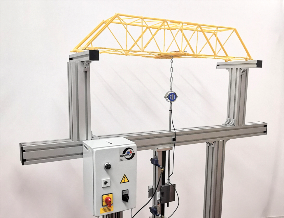
Spaghetti bridge load frame
| Maximum load: | 500 N |
| Force measurement: | Digital ring dynamometer, Tiedemann |
| Maximum support distance: | 1,5 m |
| Support width: | 250 mm |
| Drive: | Electric linear drive |
| Destroyed bridges: | 63 |
For use in load testing of spaghetti bridges, for example as part of our spaghetti bridge building competition, which accompanies the Technical Mechanics 1 lecture, but in which all students can take part.
ILH
Der Lehrstuhl für Struktur- und Werkstoffmechanik ist eng mit dem Institut für Leichtbau mit Hybridsystemen (ILH) der Universität Paderborn verbunden. Das ILH betreibt auf einem etwa 2000m² großen Technikum modernste Anlagen zur Fertigung und Prüfung von Bauteilen und vereint Expertisen aus Maschinenbau, Werkstoffwissenschaften und Simulation, um innovative Lösungen für nachhaltige und effiziente Leichtbaukonzepte zu entwickeln.
Weitere Informationen finden Sie auf der Website des ILH: https://ilh.uni-paderborn.de/